When I got my amateur radio license (a.k.a HAM radio) almost two years ago, I wanted to have a radio in the car. It could be a useful tool in emergencies, when out on the highway (particularly in convoy with another vehicle), it's been handy just to have around town, and I thought it might be fun and I could learn something from it.
Hoo boy was I right about that last bit. Steep learning curve ahead.
The Goal
A properly installed mobile radio is much better than a simple handheld. Not only can it be safer to use while driving, but an external antenna provides much better reception, and integration into the car's power system means that I don't need to worry about recharging it. It can also emit much more radio power than a handheld, for longer range and clearer signals.
I wanted my setup to be able to:
- Automatically power off when the car powers off. I don't want a radio that can be accidentally left on and drain the car's battery overnight.
- Transmit and receive on the 2 meters amateur band (144-148 MHz) as well as the 70 centimeter amateur band (430-450 MHz). HF bands are an entirely different kettle of fish and need more specialized antennas and tuners, so I'm ignoring that spectrum. I wasn't particularly interested in any digital modes at the time, so FM will do.
- Transmit and recieve on the UHF CB band. These are 80 FM channels in the 476.4125-477.4125 MHz band which is governed by the Citizens Band Radio Stations Class Licence. (For Americans, think of this as a mixture of FRS and GMRS.) Equipment that operates in this range has to be type-approved, and finding amateur equipment that will do this as out-of-band operation is both tricky and technically illegal, so the simplest solution for this is to have a second, properly licenced radio.
- Recieve airband. This is AM in the 108-136 MHz range and includes aircraft, ground stations, and automated transmissions such as ATIS.
Figuring out the plan
There was a lot about this that I really didn't know and had to do heaps of research on. The most important thing was figuring out my car, where and how I could install certain things, and how to run cables.
This involved a lot of upfront research about my car, a 2019 Toyota Camry Hybrid - which mostly involved looking for blog posts and YouTube videos, since formal documents like manufacturer maintenance guides seem to be locked away behind high costs and specialist access, and the few that I did manage to find for free were utterly incomprehensible to my non-car-mechanic mind.
I also had to be very careful about things that could ruin the car or cause damage to it or any passengers, such as obstructing airbags, correct voltages, current draw, and position and momentum of objects in a collision.
I ended up find a few useful technical resources such as installing a subwoofer, installing an amplifier, and quite a lot of UHF CB installation videos, many of which I found to be useless.
The standard operating procedure to install a two-way radio is:
- Find somewhere to install the radio unit
- Mount the antenna to the outside of your engine bay
- Run the antenna cables and power cabling through the "firewall" (a panel that separates the driver and front passenger area from the engine bay) to the radio
- ???
- Profit!
I had a few big problems here:
- My car didn't match the other Toyota Camries of the same generation as in the videos I found. Since mine is a Hybrid, the 12v auxiliary battery is actually located underneath the boot.
- I couldn't find anything that would let me install an antenna either on the outside of the engine bay, or as another idea I got from observing Police sedans, on the outside of the boot.
- I had no way to run any cables from the engine bay through the firewall. The engine bay in the Hybrid is absolutely packed and you can barely see down through it, let alone fit your hands down there. Power tools were entirely out of the question.
Actually, I really only had one big problem:

The plan (figured out)
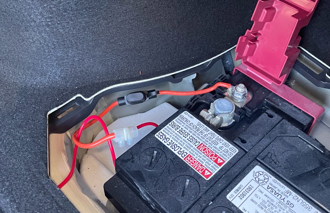
After talking with a lot of people, including members of the Waverley Amateur Radio Society, members of Amateur Radio New South Wales, my grandfather, xssfox, the6p4c, and ';drop table foxes;- (who since then has published a video detailing their own land mobile radio installation), I came up with the following plan:
The plan wasn't too difficult, and something that I actually thought I had a decent shot at achieving:
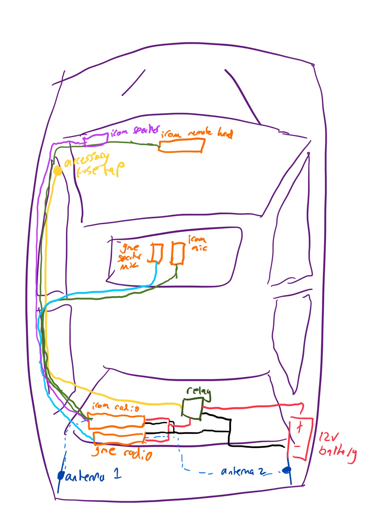
The installation would involve two radios - an ICOM 2730A for the amateur bands, and a GME XRS-330C for CB use.
The key part of the plan that made everything come together is to install both radios in the boot, drawing power directly from the 12v battery that is also in the boot. The power runs through a relay, so they get power when the car has accessory power and they lose power when the accessory power is turned off. This ensures that the radios get a clean supply of power rather than power that has already been around half the car and can be carrying radio interference from other components.
It also ensures that I can draw large amounts of current as most of the normal places where you would get power from in a car, such as 'cigarette lighter' sockets, can't provide enough. I needed up to 17A to run both radios at maximum power simultaneously - 15A for the ICOM unit and 2A for the GME. (Although the ICOM unit at high power would exceed the priviliges allowed under my current amateur licence, I didn't want to have to rewire the whole car when I upgrade my licence class one day.) The cigarette lighter socket up the front is only rated for 10A (even though it has a 15A fuse attached, don't ask me, ask Toyota).
For the relay, I made sure to purchase one with an inbuilt diode, which prevents a very high-voltage discharge when the power is disconnected. (If you want to see what the discharge looks like, check out this simulation.)
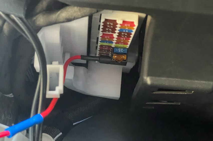
To drive the relay, I installed a fuse tap in the internal fuse block by the front passenger seats, to drive the relay. I needed to make sure to tap a fuse that provides accessory power, rather than constant power, so I ended up tapping the fuse that controls the cigarette lighter socker.
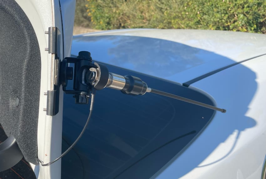
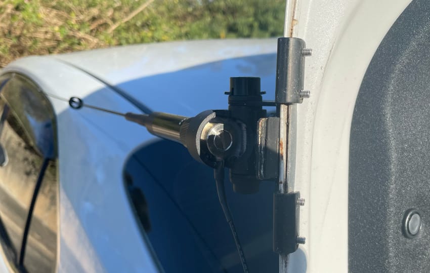
For antennas, I got a Diamond NR770HB for the amateur bands and a RFI CD51-68-50 antenna for CB, which I later had to tune by shortening it. These were to be mounted to the lid of the boot - which was not my preference, but it works well enough.
To mount the antennas, I got these very generic-sounding TWAYRDIO SO239 ones from Amazon, but the RG58 cables was too thick and started damaging the paintwork on the car by kind of pushing the paintwork out of the way. I later replaced them with Diamond K400C brackets, but there's a part of those that sticks out and it ended up scratching the paintwork too. I finally fixed it by bending that metal flap out of the way with some pliers.
I also got a Diamond-branded speaker that I really didn't like, and ended up replacing it with this very generic one from Amazon.
Lastly, I got a bunch of little things - cables for power, longer cabling for the remote head, Anderson plugs, crimping tools, extra fuses, an inline fuse, a housing for the relay, and so on.
Installation
Radios and Relay
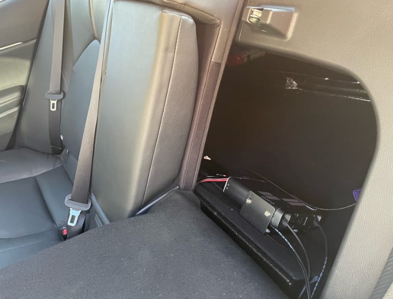
In the Camry, the bottom of the boot is basically a giant piece of fuzzy cardboard that can be lifted out to access the spare tyre. This seemed like the perfect place to install the radios and relay without drilling into any "serious" part of the car. If/when I need to access the spare tyre, the panel can be lifted rather than removed (I'm pretty sure that's how it is intended to be used anyway), or worst-case I can unplug the radios to lift out the panel and get to the tyre.
Power
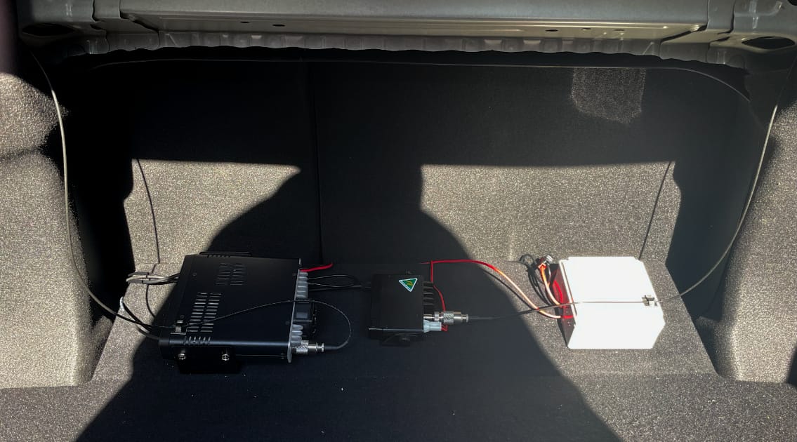
To get power from the battery, we simply added a cable under the bolt of the battery's positive terminal. This is protected by an inline fuse before the rest of the cable takes it to the relay.
It was surprisingly easy to run the positive lead underneath the interior lining of the boot and keep it out of sight. It turned out to be very difficult to run a negative lead back to the battery as the terminal for that is out of reach, so it was instead termimated to an exposed part of the chassis (as the entire chassis is a ground in most cars).
For the relay, I tapped the 15A fuse that powers the regular 'cigarette lighter' socket. This fuse is located under the front passenger's dashboard area. With the fuse tap in place the fuse block's cover no longer fits, but I don't have a good solution to that other than just leaving it off.
Interior Cabling
Next was all the regular cabling. I discovered that the trim across the bottom of each door frame pops right out, and not only did Toyota already use the little trench there to run their own cabling, they had left a second channel that I could use to run my own cables.
I ran cables out of the the boot, under the rear passenger seat's hinge and under the rear passenger seatbelt into this little channel.

I couldn't pull the cables all the way through the trench, so they run out under the trim, between the front passenger's seatbelt and the 'B' pillar, and then back under the front trim.
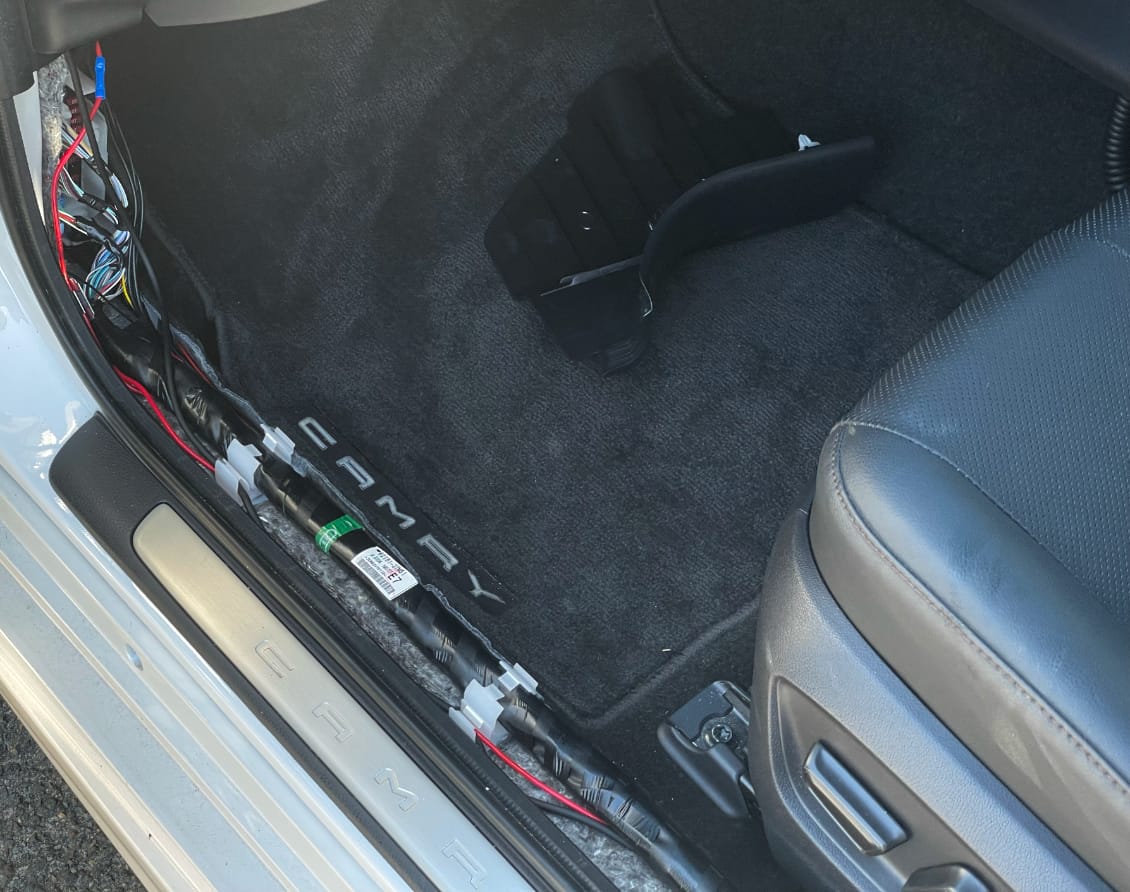
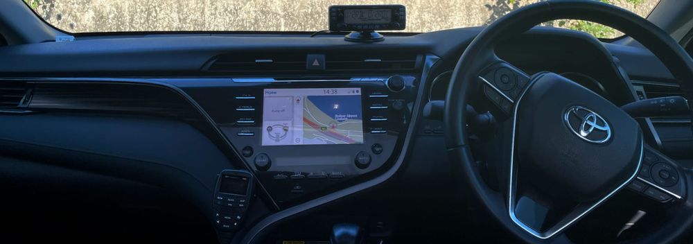
From here the power cable joins up with the fuse tap mentioned earlier. The ICOM remote head cable follows up the 'A' pillar to the top of the dashboard, and several other cables take a shortcut to the center console by travelling under the front passenger's seat.
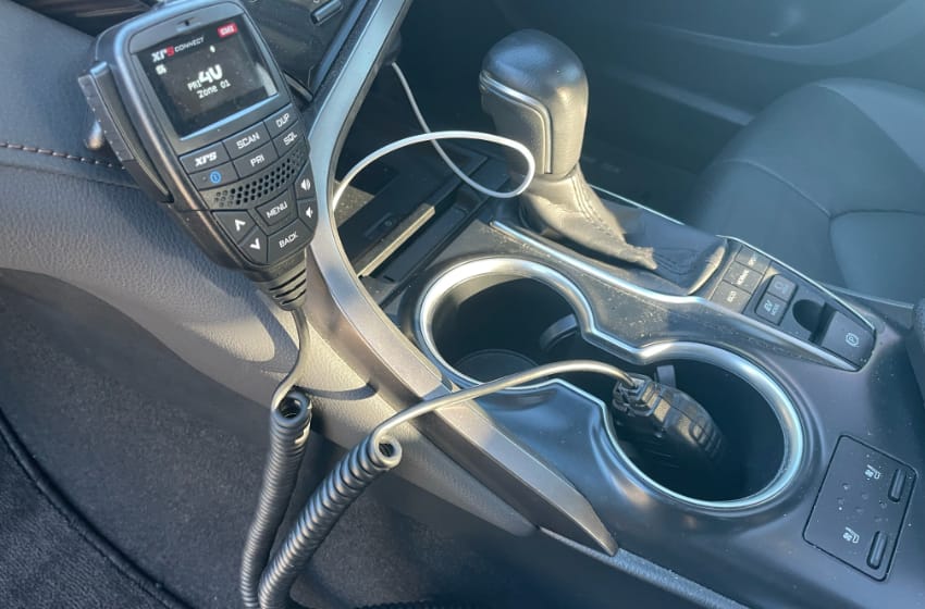
Under the passenger seat are two RJ45 couplers, and plugged into them are the GME speaker/mic/control unit as well as the ICOM microphone. These vastly extend the length of the cable and let me keep the curly springy bit where I need it.
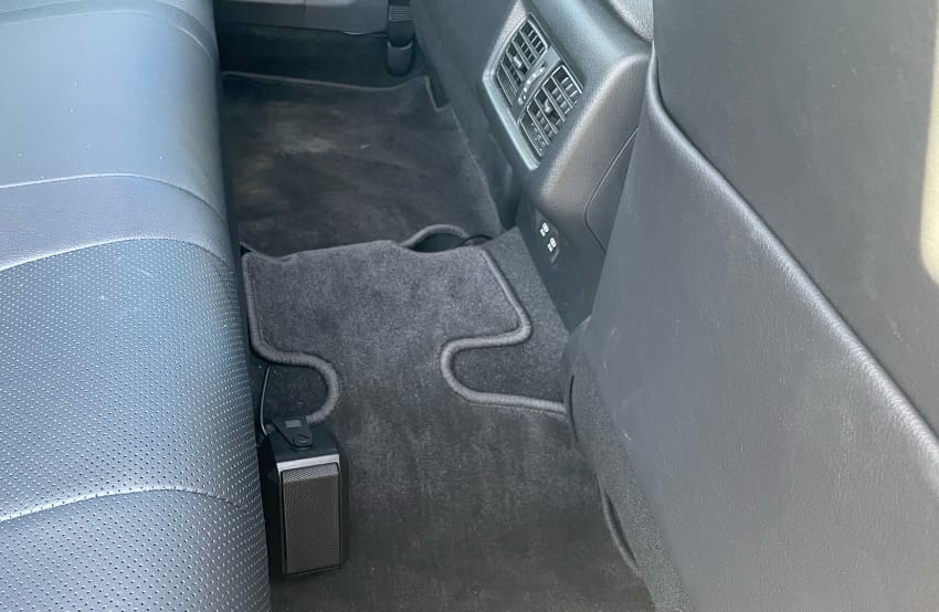
The last cable goes back into the rear to the speaker for the ICOM radio, as its microphone does not have an inbuilt speaker. This speaker here is just tucked around a perfectly-sized flap of the floor mat, it's not screwed in, and that seems to be working just fine.
Antennas
Lastly, the two antennas are mounted with the brackets that I mentioned above. This just required a bit of experimentation to get the right position, following the instructions, and bending the... flange? as mentioned above.
Conclusion
In doing this I learned a lot about electronics, automotive electronics, and how cars are assembled. I made some potentially-expensive mistakes along the way, but nothing catastrophic - nothing that required calling a professional installer or mechanic - and fortunately it all works just fine in the end.
I owe a huge amount of thanks to those who helped me along the way, including those who I mentioned above, and those who produced the videos and other resources I used to learn from (most of which are also linked above).
I hope that this blog post helps somebody else in future who is making a similar attempt.

